Connecting Video Water Blocks
Connecting multiple video blocks can be a challenge due to their usual close proximity. Serial vs. Parallel configurations each have their own pros and cons as well. Koolance offers the following recommendations for installing graphics card water blocks.
Nozzle Orientation
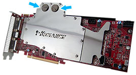
Nozzle Socket Plugs
Koolance VID-series water blocks use "pass-through" style nozzle sockets. This means the inlet and outlet nozzles can be placed above or below the water block (or both, which we'll discuss later). The side opposite each nozzle is blocked with a socket plug.
Coolant only needs to enter the "left" side and exit the "right" side of the water block (or vice-versa).
Below are four side views illustrating different nozzle configurations. All are valid and will offer identical performance:
Multiple Video Water Blocks
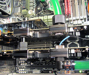
The pass-through design has additional benefits. When multiple video blocks are installed, they can be neatly connected together. This is done using traditional tubing and nozzles, or with specialized Koolance VID Connectors. Connectors allow for close installation that is difficult to achieve with tubing.
Blocks Connected With Tubing
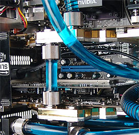
Blocks Using VID Connectors
Choosing VID Connectors
When using connectors, you need to determine which length is necessary for your motherboard. Simply count the number of motherboard slots or chassis L-brackets in between the final video card positions. (When counting L-brackets, double-height video brackets should count as two spaces.)
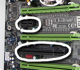
Count Slots in Between Video Boards
(or) Count L-Brackets
The image to the left shows one (black) slot in between each PCI-E 16x (green) slot. If a video card was installed into all three green slots, a "1 Slot Spacing" CNT-VD connector would be used between both video water blocks. However, if only the first and third green slots were used, a total of three slots now exist between video cards (black->green->black). Therefore, a "3 Slot Spacing" CNT-VD connector would be needed. For the diagram to the right, a "2 Slot Spacing" VID connector is needed.
It should be noted that dual PCB video cards like the original GeForce GTX 295 and 9800 GX2 utilize different slot spacings. Although they are only inserted into one PCI-E 16x slot, the water blocks themselves are thicker and can not utilize this method of slot counting.
Series and Parallel
Like nozzle orientation, CNT-VD connectors can be installed in different ways. Principally, coolant can be be run in series or parallel through multiple video blocks.
Two Blocks in Series
Three Blocks in Series
Two Blocks in Parallel
The configuration you use depends on your individual cooling system. A common misconception is that running parallel paths in the same loop is always better. Experimentation is usually suggested. Keep in mind that parallel lines reduce coolant pressure, so results will depend upon the pump and tubing configuration. In a serial system, only 2-3°C is typically added between video blocks.
To illustrate this point, let's say two video blocks are connected in series. The first video block is operating at 45°C, while the second is at 47°C. This is disturbing to some users. They want both video blocks at exactly the same temperature, so the blocks are reconnected in parallel. However, due to the pressure decrease of parallel paths and additional restrictions in the loop, both cards may now operate at 48°C.
Stay Connected